In order to build the support pillars for the frame, the size of the gear stack must be determined. The gears on the driven stack all rotate independently and should to move freely. Consequently, a set of bronze spacers between the gears and between the top and bottom gears and the top and bottom frames were made to function as bearings. Five bearings were needed for the driven gear stack and five for the driver gear stack so gear heights would match. All 10 were made from 1/2" bronze rod. The design was a simple washer: 1/16" thick, 1/2" in diameter and with a hole sized according to the largest tube/rod that would pass through it (1/8", 3/16", 1/4", 5/16", and 3/8").
The bottom washer on the driven stack is unique in that it needs to be thick enough to span the worm wheel plus the two washers on either side of the worm wheel.
A 5" length of 1/2" bronze rod was held in the three jaw chuck and supported with a steady rest. The end was faced and center drilled. After drilling about 1" deep with a #31 drill the hole was reamed with a 1/8" reamer in the lathe. A 7/16" length was cut off with the cutoff tool. The hole was opened with a #15 drill bit and reamed with a 3/16" reamer. The cutoff tool was moved its thickness plus 1/16" and a second spacer was cut off. The hole was then drilled with a 15/64" drill bit and reamed with a 1/4" reamer. Seven bearings were cut for this size hole (6 on the driver gear stack and 1 on the driven gear stack). This process was repeated producing spacers with openings of 5/16" and 3/8" as well. The spacers were cleaned up with some countersink work and a little filing.
Decided to use the 26 tooth ~1/4" worm wheel instead. Also realized that the worm is 1/2" in diameter so the gears need to be raised accordingly. The bearing holes in the worm bearing blocks are centered 5/16" high. The worm wheel is 0.267" thick, putting its center 0.134" high. The washer below the worm needs to be 5/16" - 0.134" = 0.179" thick. The washer above the worm wheel needs to raise the bottom or Mercury gear above the worm bearing blocks, so it should be 7/32" thick. This means that the bottom washer on the driven gear stack should be 0.179" + 0.267" + 0.219" = 0.664". The two washers above and below the worm wheel were made with 1/4" holes and the larger driven stack washer was made with a 1/8" hole.
The frame was designed with a brass bar spanning each dodecagon. The bottom span will support the gear stacks and the worm, while the top span will support the top of the gear stacks and provide support for the rings. A 3/16" X 2" brass bar was purchased for the bottom span and a 3/16" X 3/4" purchased bar was destined for the top span. On second thought it might ber easiest to screw the spans to the dodecagons. 1/4" bar stock rabbeted on both ends could be screwed on and not be visible if the rabbet runs under the dodecagon.
Support for the rings, especially the Mars ring as it is so large, was considered necessary. Each ring would be supported by the ring below it using 3 or 4 ball bearings seated in a small hole drilled in the lower ring just below the outer ring of each planet ring. The Mars ring as it has no "lower" ring is to be supported by two ball bearings on the upper frame's span and by adding two small bumps to the inside of the frame holding two more ball bearings. The "bumps" will have rabbets and be screwed to the underside of the dodecagon frame at 90° relative to the span.
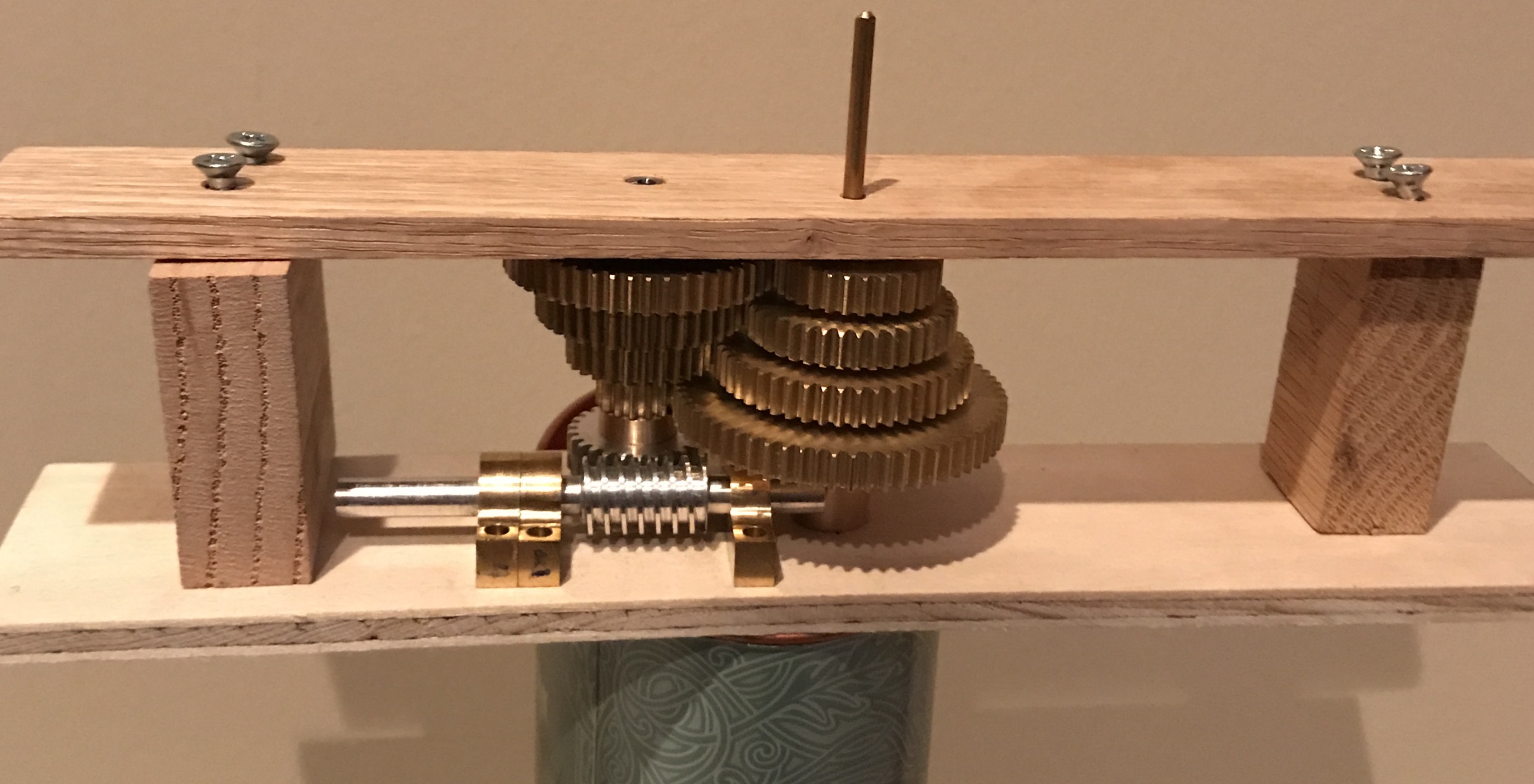
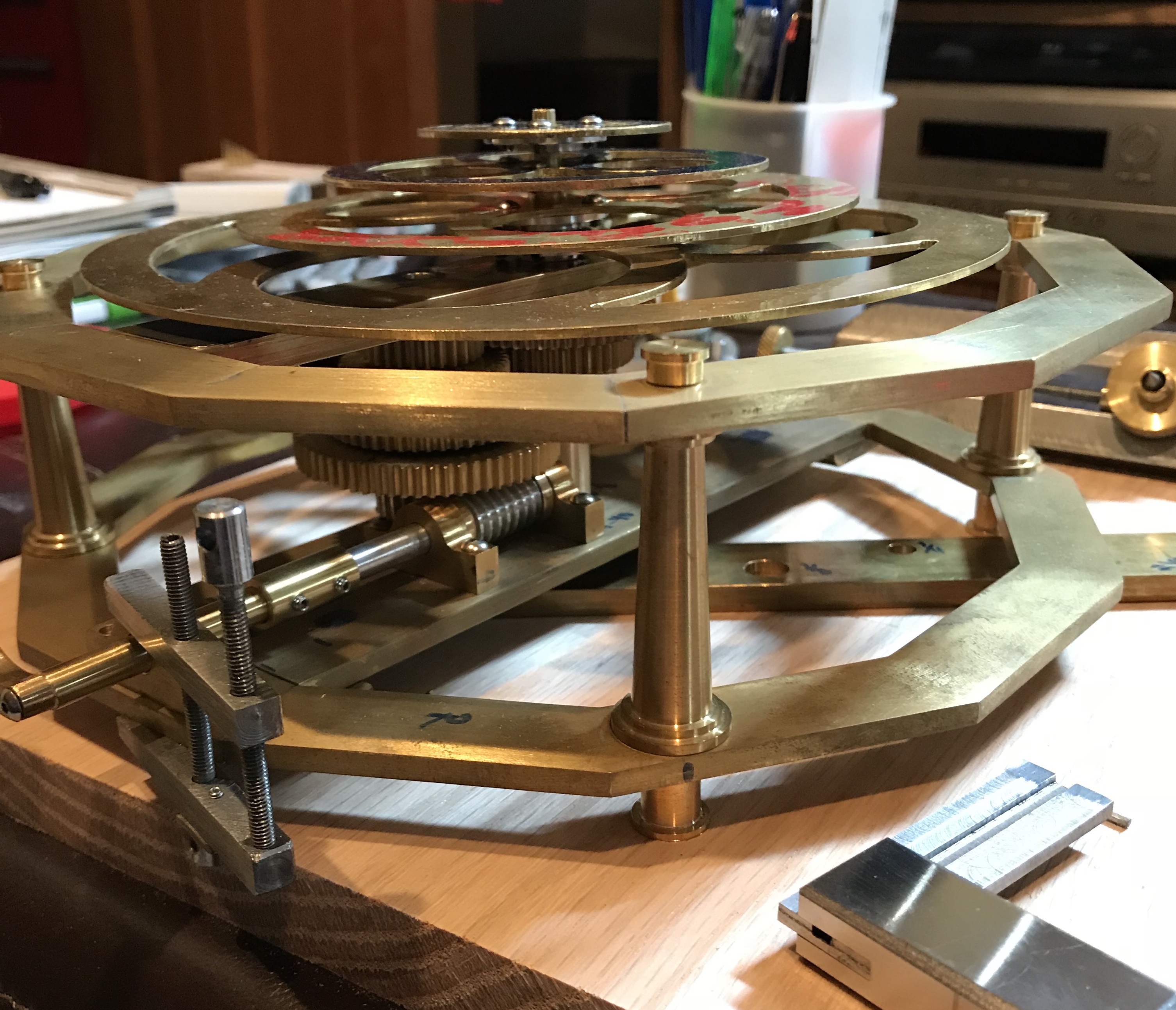
The next task was to determine whether the gears, bearings, and spacers were sized correctly. To do this a mock up of the eventual support bars was made from wood. Two 1/4" thick pieces were cut to 9". One was 2 1/4" wide and served as the bottom support. Two blocks of wood were cut to the same length as the columns, 1.934". A center mark was made for the driven gear shaft and the depthing tool was set and an arc was made. Along this arc and 7/16" off the center line a mark was made to indicate the position of the driving gear shaft. The two wooden supports were clamped together and a 1/4" hole was drilled for the driving gear shaft and a 1/8" hole was drilled for the driven gear shaft. The two blocks were drilled and screwed to the bottom support. Through holes were drilled in the top support and these holes were transferred to the tops of the blocks and drilled. The two gear stacks were put in place and the top support was screwed in place. The vertical alignment of the gears was perfect. The gear center to gear center distance could not be assessed as the gears in the driven gear stack do not have 1/8" center holes. The placement of the holes did allow testing the location of the worm and brackets. This seemed fine, however the worm shaft pointing toward the driven gear stack needs to be shortened about 1/4" as it bumps into the bottom bearing. A picture of this mockup is below.
The bottom support bar was cut from 3/16" X 2" brass bar stock to 7 5/8". The ends were cleaned up and made parallel in the mill vise which had been indicated in. The length was reduced to about 7 9/16" by checking the fit with the bottom dodecagon after removing burrs with a file. The two mating sides of the dodecagon were marked with a Sharpie as the dodecagon is not perfect.
Two supports were required to attach the bottom support bar to the dodecagon as a decision was made to stick with the 3/16" thick stock for the bottom support. A simple sketch is shown below. The bracket will use four round head 4-48 screws. The support bar will have 1/8" deep tapped holes in both ends to attach to this bracket. Similarly, the dodecagon will have 1/8" deep tapped holes as well to attach to the bracket. In this way the screws will be hidden from above. The screw size was selected for two reasons: it gives sufficient threads for good holding and this size bottoming tap is available in in my collection of taps.
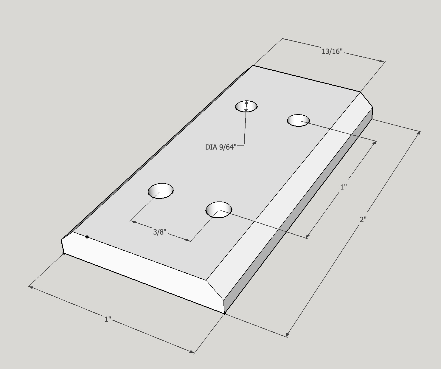
Two 1.06" lengths of 3/16" X 2" brass were cut off with the bandsaw. The first part was set up in an indicated vise and one long side was cut perpendicular to the short sides. This part was then placed against the angle plate (again indicated square) supported on the square side with parallels. It was clamped with two machinist's clamps. The unfinished edge was cut flat with a 5/16" end mill and the width reduced to 1.0". This edge was then cut with an 82° included angle countersink to a depth of 3/32". The part was flipped over keeping the same face against the angle plate. The angled cut was then repeated on this second side. This was repeated on the second bracket, but it was started directly on the angle plate. It was aligned with a square on the side before milling the first side.
A bracket was put in the vise and the holes were drilled (0.140") by locating edges.
Note the measuring was incorrect so the holes do not match the plan above. It should, however, not matter as the holes will be transferred to the dodecagon and bottom support.
The next task was more carefully depthing the gears to set the distance on the bottom support. The Earth gears were placed on the tool and the depth set so that they rotated freely. The Mercury gear pair was placed on the tool with the retained Earth setting. They fit well, but there were a few places where intermittent sticking occurred. The gears were removed and the offending teeth were slightly filed with a three-corner file. This was repeated until no more sticking was felt. This was same process was followed with the Mars and Venus gear pairs until they also rotated freely at the same depthing tool setting. The depthing tool was now ready to transfer the correct distance to the bottom support.
The Venus and Mars gear pairs were significantly off when initially placed on the depthing tool. One did not even touch and the other could not be put on the tool as the gears were too close. I then realized that two gears were swapped between the pairs! Ascertaining which gears were paired lead to perfect fits. These gears were then labelled and all gear pairs were strung together with twist ties!
With the correct dimension set on the depthing tool it was time to complete the bottom support. The length of the bottom support was measured with the height gauge, while supported by a 1-2-3 block. It was found to be 7.597". A Sharpie was used to dye the center of the support and the height gauge was used to scribe a line at center, 3.799". The height gauge does not measure as low as 1", so the bottom support was set sideways on a 1-2-3 block supported in back by another 1-2-3 block and a line was scribed with the height gauge at the center of the support. A small punch was used to make a divot at the intersection of these two scribed marks. The Sharpie was then used to dye an area where the arc of the depthing tool should lie. One point of the depthing tool was placed in the center divot and an arc was inscribed on the bottom support. The distance above center line was determined empirically. The worm wheel and spacer was placed on the arc and the worm supported in its bearings was held so the teeth were meshed. The worm wheel was then moved along the arc so that the ends of the worm bearings were centered to either side of the wheel and the bearing ends were about 1/16" from the side of the support bar. A transfer punch through the worm wheel then marked this position on the arc. The exact distance above center is not critical as long as the hole is centered on the arc.
That process is much too complicated and prone to error. What is needed is a depthing tool for the worm and wheel.
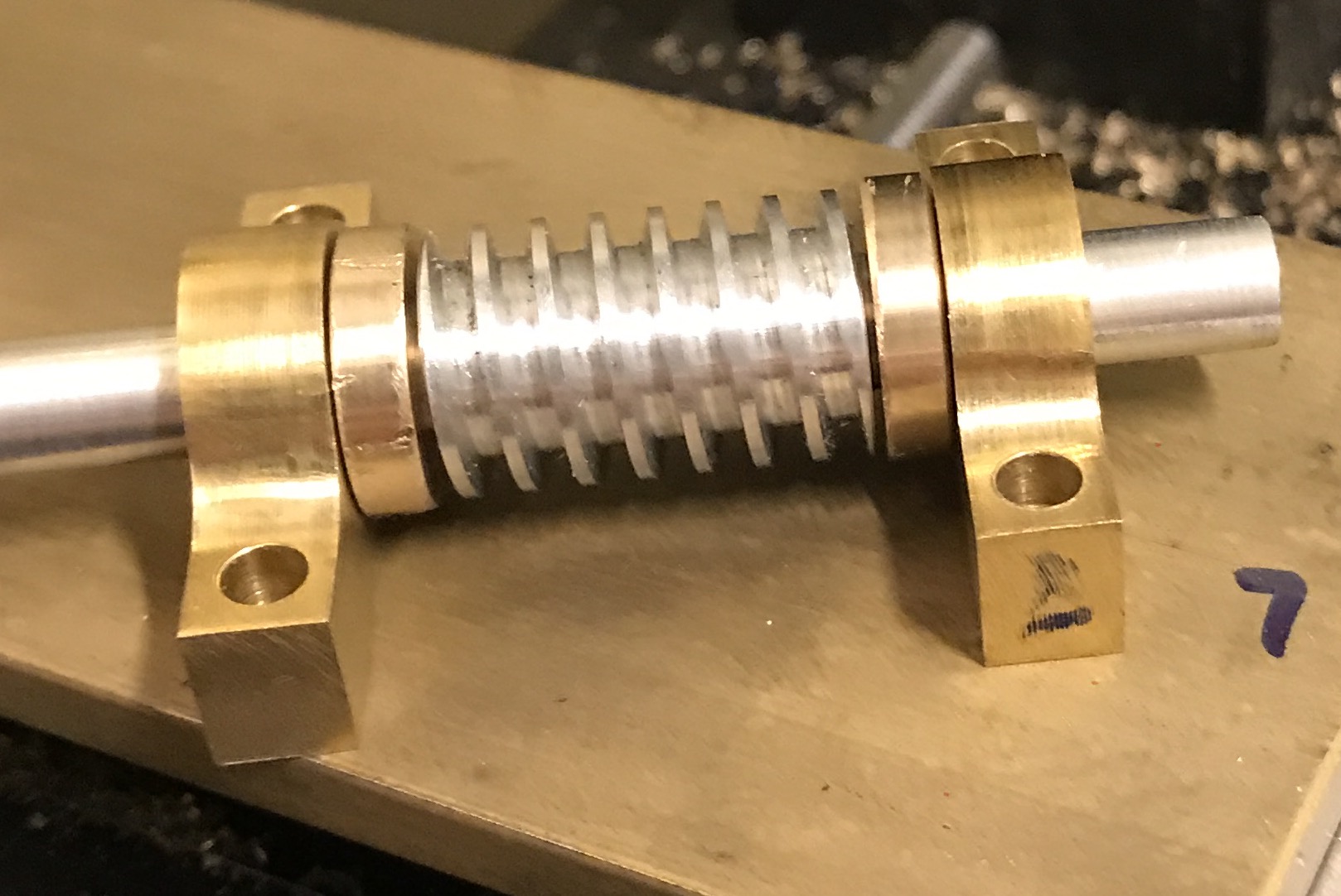
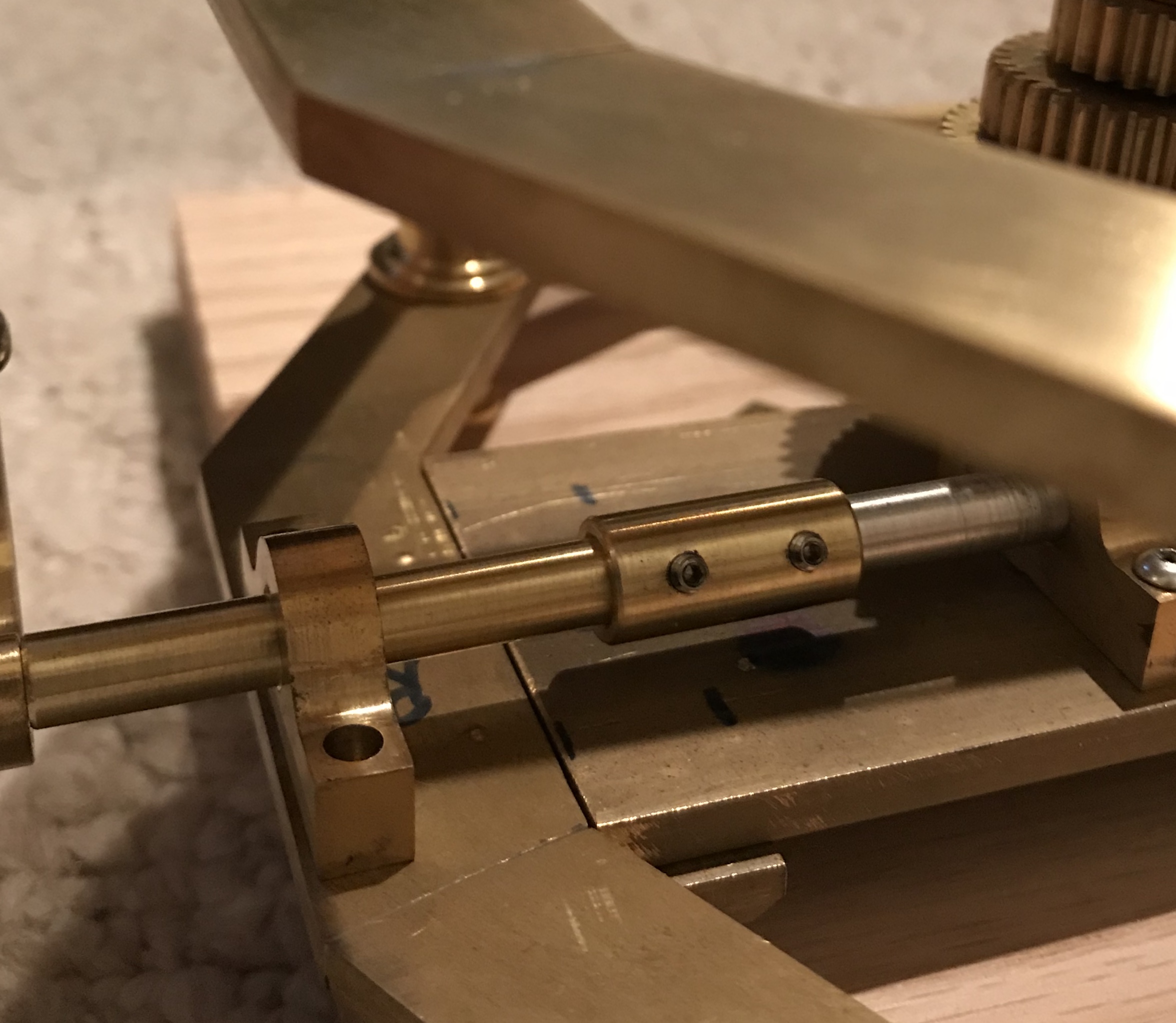
Setting the distance of the worm and its bearings was tackled next. First, some housekeeping needed to be done on the worm shaft. If the worm is not constrained on both sides it will move in preference to turning the wheel. The plan was to use spacers between the worm and the bearings as the bearings needed to be about 1/8" from the ends of the worm threads. This provides sufficient room for the bearings to span the worm wheel with no contact. Two spacers were made from 1/2" bronze rod. A 1" length was placed in the 3-jaw chuck and the end was faced. The diameter was reduced just enough to reveal bright bronze for about 3/8". A hole was drilled and reamed 1/4". The spacers were then parted off at 0.125" each. These fit nicely between the worm and its bearings as seen in the picture below.
The end of the worm shaft was too long and pressed against the bottom bearing on the driven gear stack. Consequently, it was held in a collet in the lathe and about 1/4" was parted off.
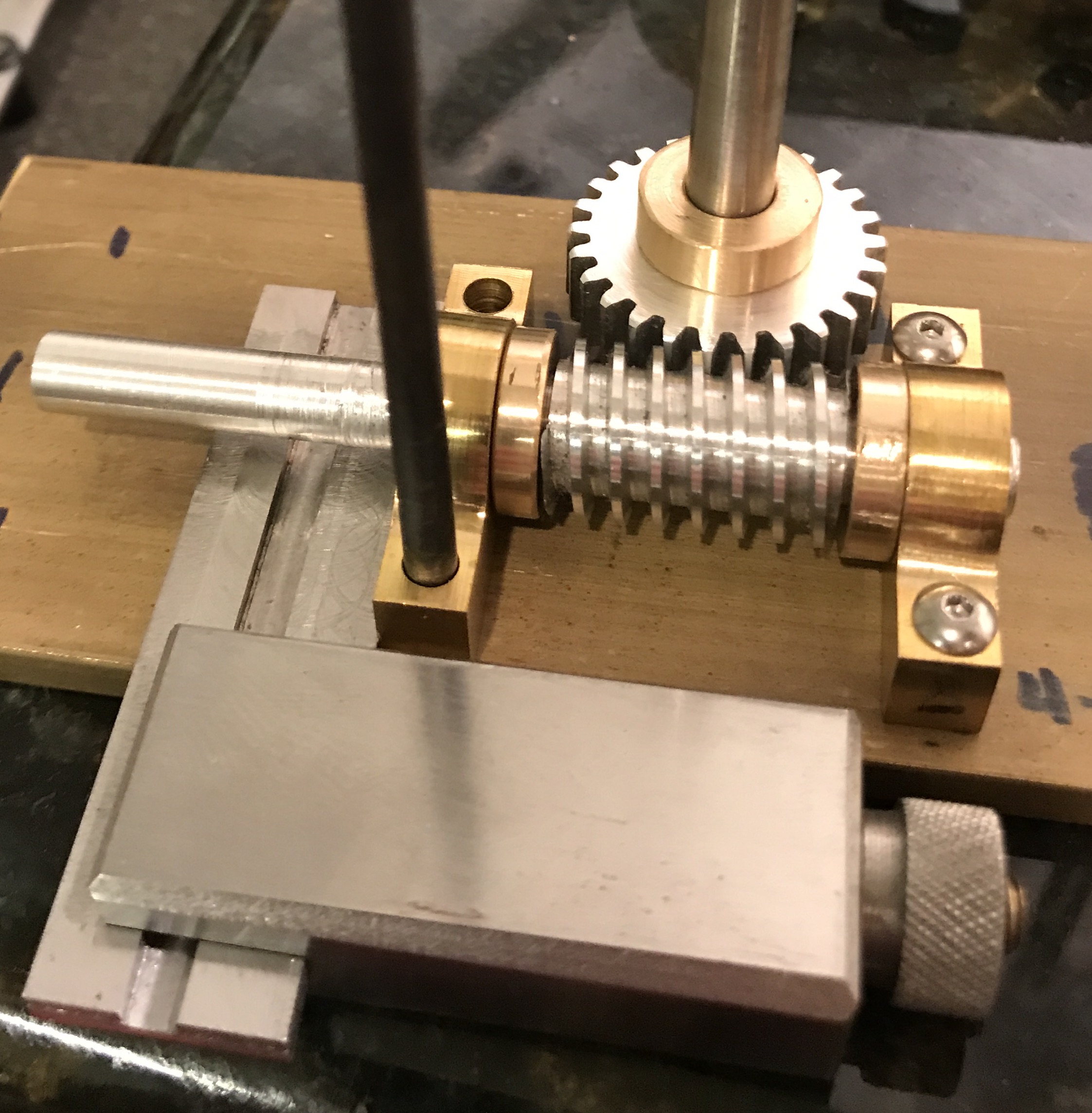
The bearings were aligned with the worm in place against the worm wheel on its axle. Unfortunately, the only way I could manage proper alignment was by eye. The rightmost bearing was moved until I felt that the worm and wheel were properly aligned for fit. The location of one hole in the bearing block was then transfer punched to the plate. The transfer mark was enlarged with first a prick punch and then with a spring loaded punch. The hole was started with a 1/16" drill and drilled through with a #43 drill bit. The hole was then tapped 4-40 and deburred. The bearing block was screwed to the plate with one screw and again adjusted to get a good fit between worm and wheel. The second hole was then transferred, had its mark enlarged, drilled, and tapped. This process was repeated for the next two bearing holes. In each case the worm and wheel were checked for proper engagement. When all four holes had been drilled the assembly was screwed together. There was some binding when the left bearing block was screwed down. If pushed to the back of the plate while tightening the screws all was well and the worm and wheel moved freely. [After having assembled the entire orrery and turning the handle to drive the gears via the worm the orrery was taken apart to begin polishing and decorating. Some aluminum dust was found below the worm. It is not clear if that is just wearing in or if the worm and wheel need to be remade of something harder like brass or bronze.]
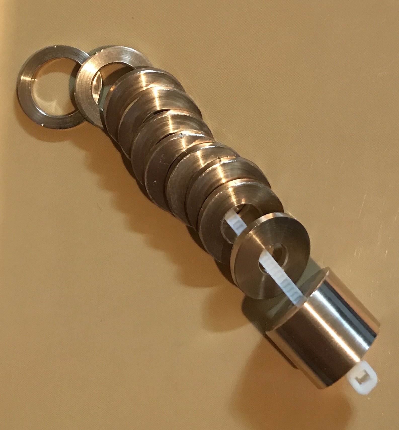
The driver gear stack needs to be fixed in place so all gears will rotate in sync with the worm wheel. I don't have the capability to make a keyway in the gears. Preferably the "attachment" is reversible so gluing is out. A shaft through each of the gears and the worm was the preferred methodology. A 0.082" brass rod was handy, so a #44 (0.086") drill bit was chosen. The process used to assure hole alignment was as follows. A few years ago I madea 3/8-16 bolt with a 1/4" shaft as a center spigot for my rotary table. This was screwed into a 1-2-3 block. The block was set on its side and the top two gears from the driven gear stack were placed on the vertical shaft and held in place using two step clamps. The table was adjusted so that the spindle was centered over a point on the topmost gear 3/16" in from the outer edge. This spacing avoids the washers between the gears and also fits the smallest gear (the worm wheel). A hole was drilled through the top gear and approximately halfway into the bottom of the two gears. The top gear was then removed, the bottom gear became the top gear of the next pair and a new gear is selected for the bottom position. The drill bit was carefully aligned with the hole in the top gear and drilling proceeded as before to a depth of 3/8" or halfway into the bottom gear. Repeating this process led to all of the gears drilled through except the worm wheel which was left drilled only halfway through. As you can see in the following picture all holes were well aligned and with the locking shaft in place they all turned smoothly in unison when the worm was turned.
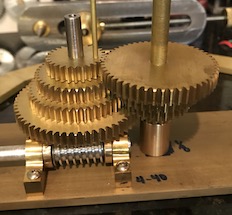
Note that none of the washers or bearings are in place in the picture above except the two spanning the worm wheel and the large bearing below the driven gear stack.
The gears are not quite finished at this point. Three of the gears on the driven stack need their 1/4" holes modified. Four tubes transfer the motion of the driven gears to the planet rings. The sun is supported on its 1/8" shaft, the Mercury ring on its 3/16" tube, Venus on its 1/4" tube, Earth on its 5/16" tube, and Mars on its 3/8" brass tube. All of the gears were made with 1/4" center holes so the same arbor could be used for their production. The Mercury center hole is too large, so a simple collar and bushing was made to reduce its diameter to 3/16". A 1/2" diameter bronze rod was held in the 3-jaw chuck, faced, drilled, and reamed to 3/16" for a depth of 1/2". A 1/4" length was then reduced to 0.25" for a sliding fit in the Mercury gear. This was undercut at the collar to make sure the bushing would sit flat on the gear. The bushing was parted off at 5/16" providing the 1/16" thick collar. The holes and corners were chamfered providing the completed bushing/collar for Mercury's driven gear.
The Earth and Mars gears' center holes needed to be opened up. The Earth gear was clamped to the milling table and centered with the aid of a 1/4" drill bit. It was then enlarged with a letter N drill bit followed by a 5/16" reamer. The Venus gear was drilled with a 5/16" bit followed by a 23/64" bit and reamed to 3/8".
Attaching the bottom support bar to the bottom dodecagon was tackled next. One of the brackets was aligned on the dodecagon about 5/16" in from the outside edge. A hole was transferred from the bracket to the dodecagon, punched with a prick punch and then with a spring punch. This hole was started with a center drill and then drilled to size with a #43 drill bit about 0.150" deep and tapped 4-40. The bracket was attached via this hole and the second hole was transferred, drilled and tapped as above. The bracket was now screwed through both holes to the dodecagon and two holes were transferred to the bottom support bar, drilled and tapped. This process was repeated for the second bracket. The holes in both brackets were countersunk approximately 0.045" with a 1/4" countersink bit. Eight brass 4-40 phillips head screws were cut off. This was done by putting two nuts on the screw all the way up to the head. Each screw was held in the lathe and parted off at the face of the second nut. This left about 3/16" thread. The end was filed slightly before the screws were put in place.
The four through holes in the dodecagon for the feet and columns were placed every third side. They were centered across the 3/4" dimension and situated 27/64" from the left joint (1/8" + the bottom column radius). This will place the top ends of the columns (diameter = 3/4") 3/64" from the joins in the top dodecagon. The hole locations were marked out and punched.
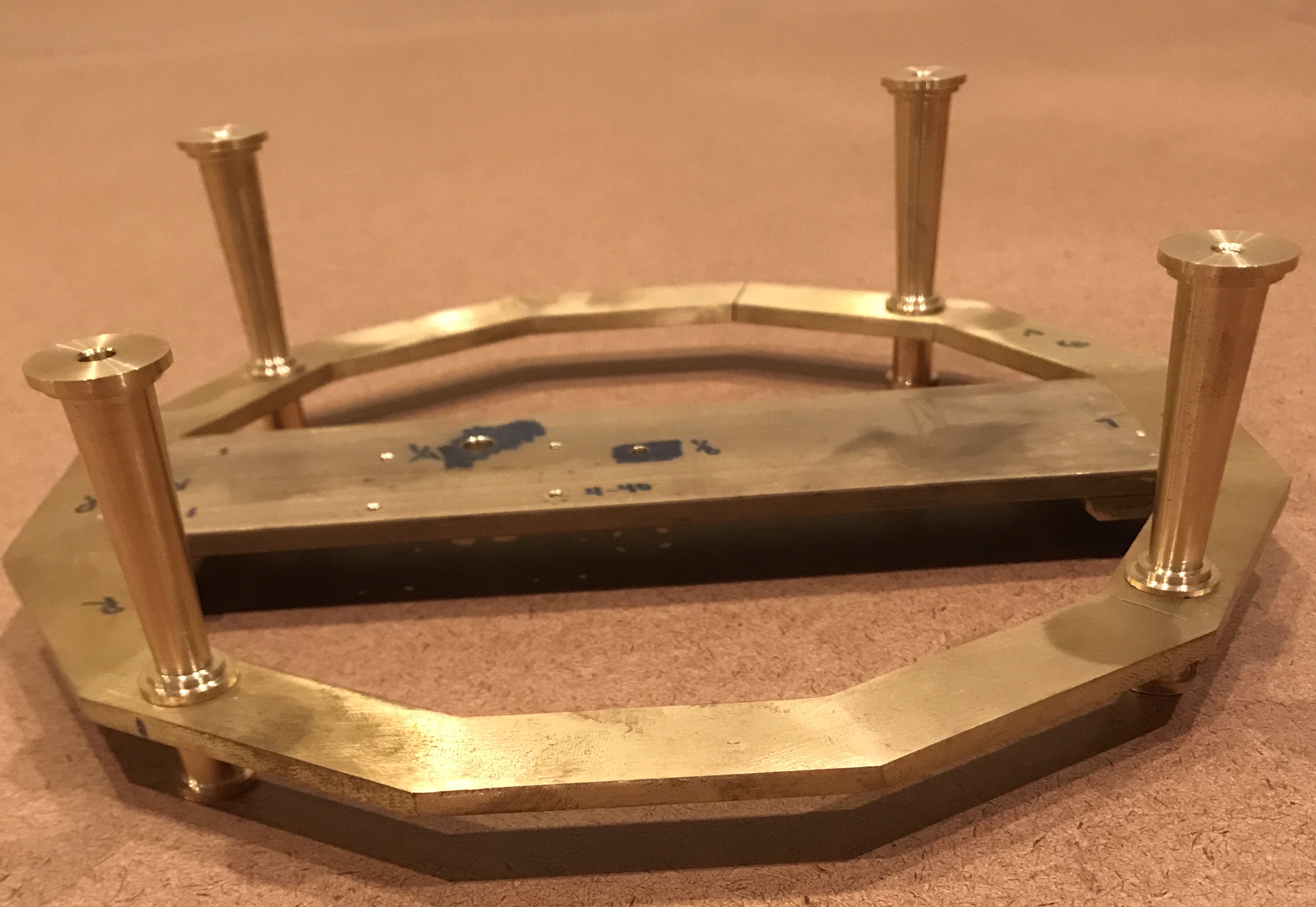
The dodecagon was held in the vise which was clamped to the milling table. A tailstock center was used to center the spindle over the punch mark. It was then drilled with a center drill, followed by a #33 drill bit, and opened to 8-36 through diameter with a #10 drill bit. This was repeated for the other three holes. A photo of the dodecagon with the feet and four columns attached is shown below.
To transfer the locations of the tops of the columns to the upper dodecagon four pointed screws were made. Four 1" lengths of 3/16" steel rod were cut with a hacksaw. A rod was placed in a collet in the lathe and the end faced and diameter reduced to 0.16" for 0.30". Using the parting tool a groove was cut about 0.015" deep 0.25" from the faced end. Threads were cut for this 1/4" length with an 8-36 die. This cutting and threading was repeated for the other three 1" rods. Each rod was then placed threaded end first into the collet. The headstock was rotated 27° and the end was tapered to a point (about 0.075" of cross feed). The resulting pointed screws were screwed into the tops of the columns and the distance from point to dodecagon was measured. Two were 1/16" higher than the other two so their screws were faced to shorten them by 1/16" making all of the points 2 5/8" above the bottom dodecagon.
The top dodecagon was marked with a Sharpie at four spots corresponding to the four columns. With the pointed screws in place the top dodecagon was put in place and two squares were used to align the two dodecagons. It was necessary to judge the rotation of the upper dodecagon by eye. Sliding the squares from side to side also helped the alignment. A thin board was used to press down on the upper dodecagon directly over two opposite columns. Each end of the board was struck with a hammer. This was repeated for the other two columns. This was not a perfect transfer as other marks were seen in the Sharpie'd areas indicating that the upper dodecagon bounced during the hammer blows even though there was significant pressure on the board during striking. Clamps will need to be used to keep the upper dodecagon from moving.
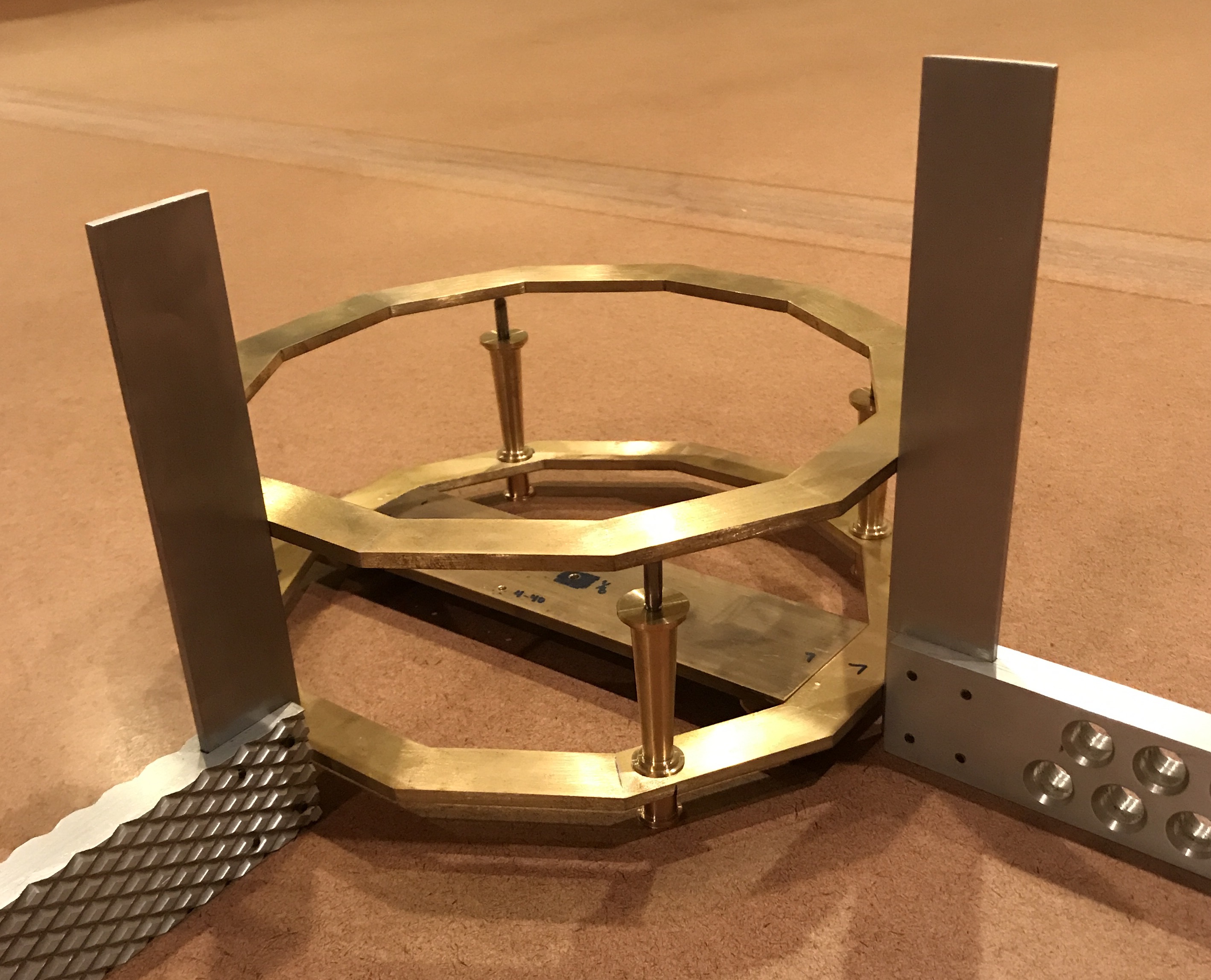
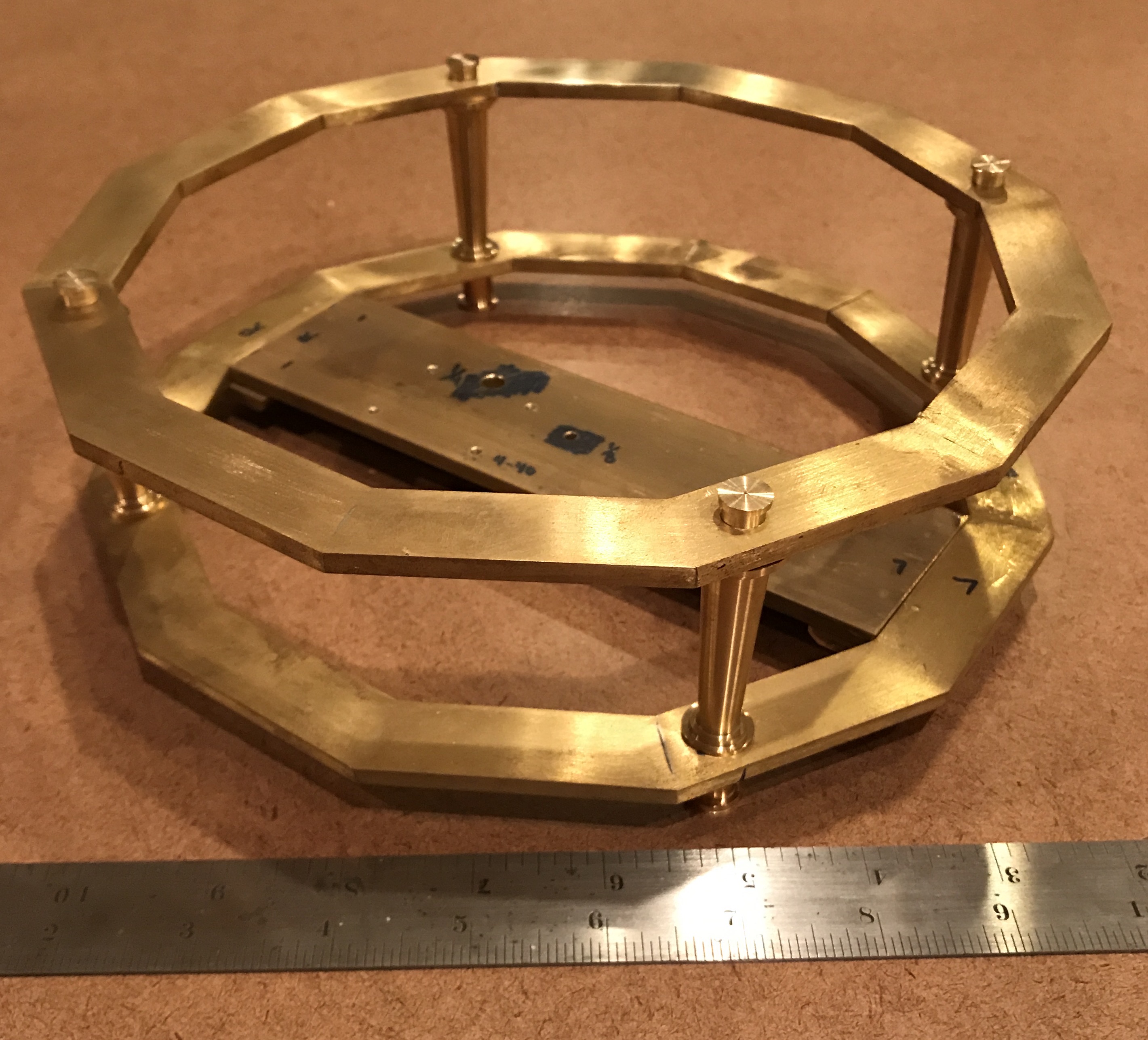
The second attempt was successful! The bottom dodecagon was rested on wooden blocks so two clamps would fit underneath. Wood spacers were used between the clamps and the brass. The top dodecagon was centered and squared up as accurately as possible and the clamps were tightened. The top dodecagon was tap with a brass hammer above each of the transfer screws. This gave nice dimples in the Sharpie'd spots. The top dodecagon was transferred to the mill vise. The dimples were centered with a tailstock center in the drill chuck. They were then drilled successively with a center drill, a #30 drill, and a #10 clearance drill for the 8-36 screws. The holes were cleaned up with a chamfer bit. The two dodecagons fit nicely together on the columns as seen in the following photo.
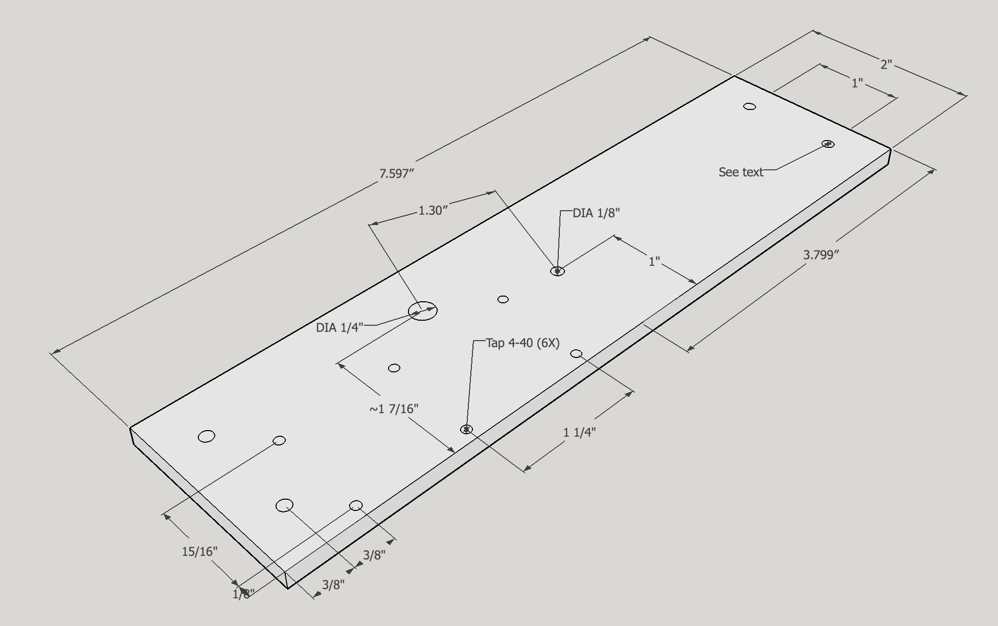
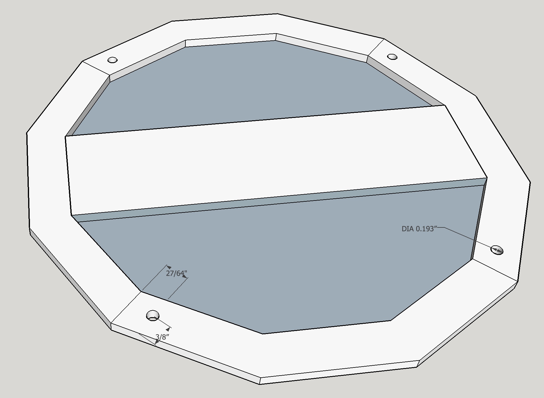
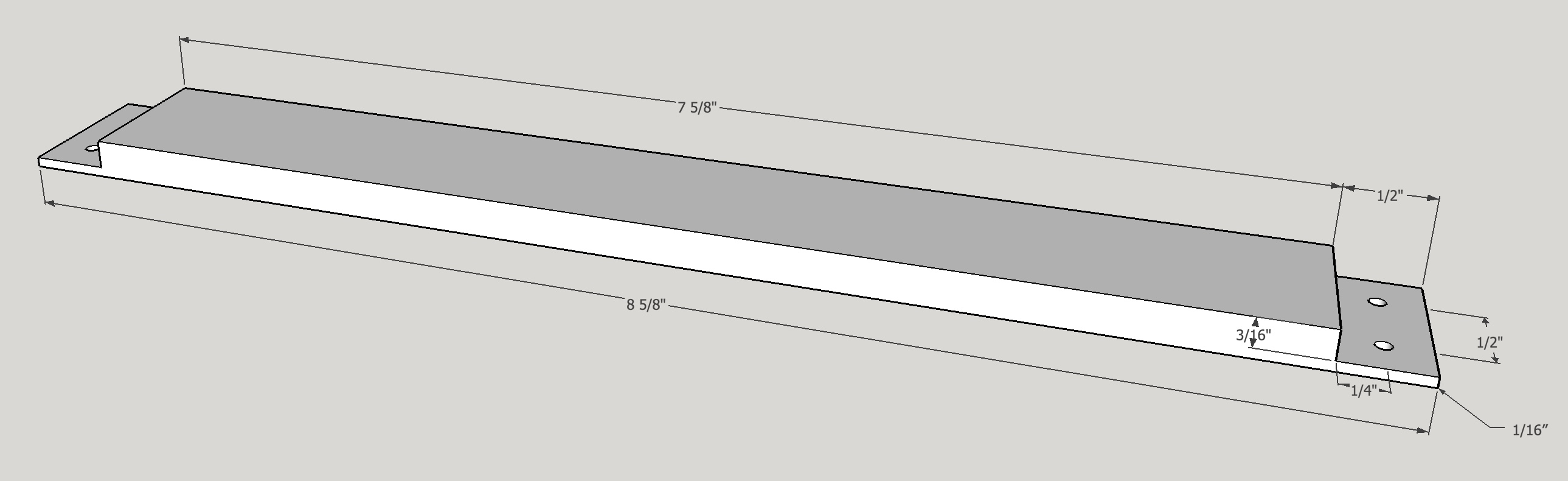
The upper support was designed a little differently than the lower as 1/4" thick brass stock was on hand. Instead of brackets to attach it, a dado was cut on the ends 3/16" deep and 1/2" wide. Clearance holes in this support and tapped holes in the upper dodecagon provides the coupling. This is shown in the plan below.
An 8 5/8" bar was cut from 1/4" X 1" brass stock with a hacksaw. The ends were squared up and the end mill was set 3/16" from the top of the stock mounted in a vise on parallels. The dado was cut in 0.015" passes on both ends. The second end was carefully measured as it was cut and then tried against the upper dodecagon between cuts to get a very close fit. Burrs were removed and corners were slightly rounded with a file. Clearance holes for attachment to the upper dodecagon were drilled in the ends. The two holes for the gear stacks were carefully transferred from the bottom support and drilled and reamed 1/4" and 3/8" for the driver and driven stack, respectively.
Damn!!! The holes were marked out when aligned with upper support upside-down. So now it will only work if it is mounted from the top.
After a brief respite to make the Tic-Tac-Toe set the upper support was remade. The previous version was used to transfer the holes. Again a tight fit with the upper dodecagon was achieved. When put in place the upper support is too tight to the top of the gear stacks. Consequently, spacers/bearings will need to be thinned a little to provide free movement. Instead of thinning a number of new washers/bearings were made in the same fashion as before, but they were made only 1/32" thick. The top three washers and bearings in each stack were replaced and this gave each stack a small amount of room for vertical displacement, maybe 1/64". The gears now spin, but they seem a little tight. The top support needs to be square with respect to the bottom support. Very slight rotations of the upper support gave more freely rotating gear stacks. The holes need to be transferred with the upper support held firmly in this position.
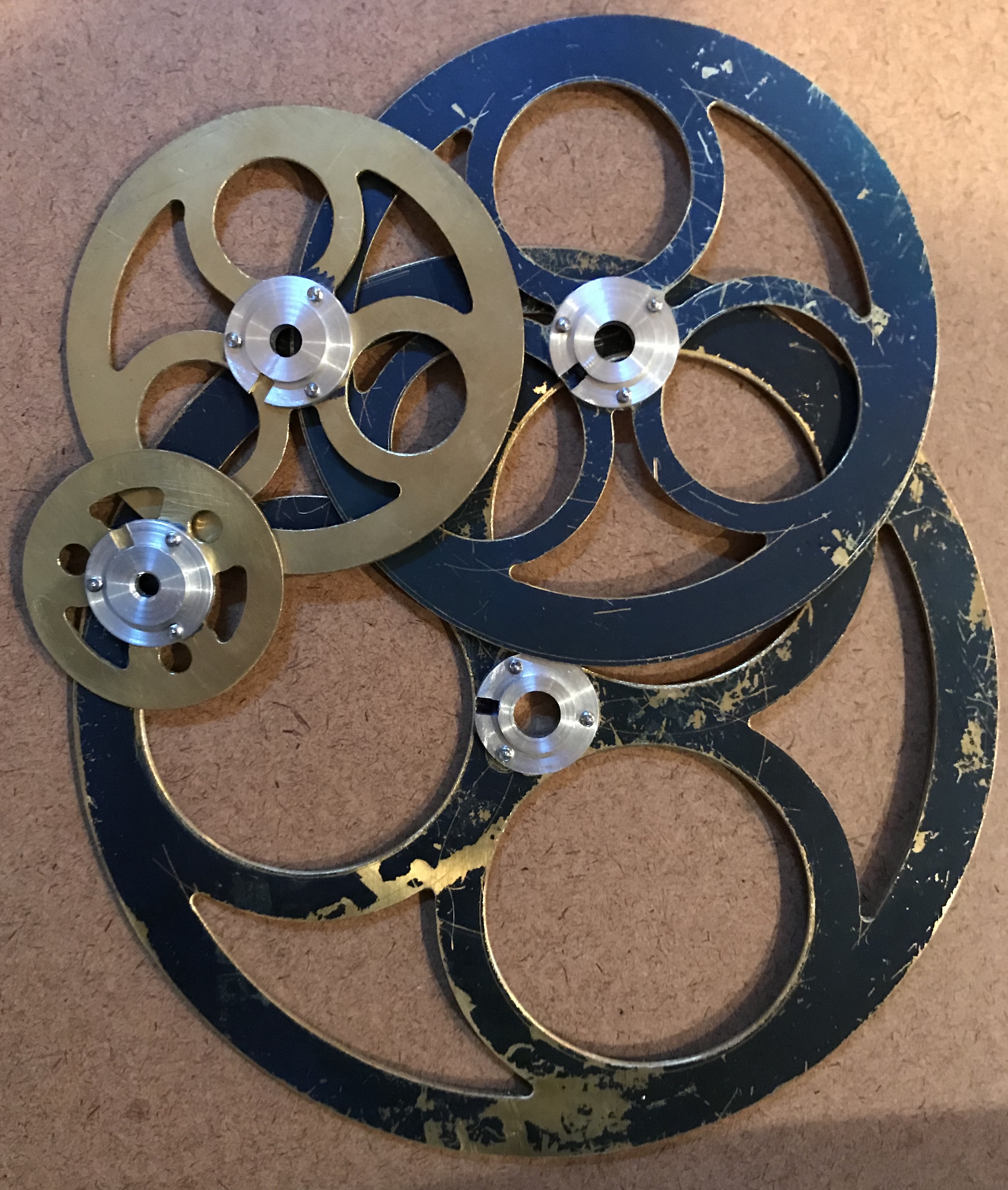
Attached the hubs to the rings this morning (2/7/18). First the center holes of the two largest rings were drilled to size: the Earth ring was drilled to 5/16" and the Mars ring was opened to 3/8". The appropriate hub was then aligned with the ring via a transfer punch. One hole was marked with a #43 drill and this mark was punched, center drilled and drilled 9/64" (4-40 through hole). The hub was attached to the ring with one screw and centered with the transfer punch. The other two holes were then marked and drilled as well. The screws were cut off in the lathe to the length of two nuts. This is a little longer than needed, but short of thinning the nuts it was found acceptable. The short screws were then used to attach the hubs to the rings, while centering with the appropriate transfer punch.
The hubs need to sit on the top face of the rings. This provides access to the set screw for orbital adjustments and for removing the rings from the tubes. Turns out this is not necessary. The hubs can sit below the supports, if the set screws are aligned with the rings allowing access.
Next up was cutting the tubes to length. Each tube's length is the sum of its gear and washer, the previous tube, the width of the top support (for Mars only), the space between rings (0.100), and the width of the hub/ring combo (0.204). The Mars tube was cut first. This 3/8" tube was 0.830" long (0.272 + 0.252 + 0.100 + 0.204). The tube was parted off at length and both ends chamfered inside and out. The tube was also reamed, in this case to 5/16". The Earth tube was cut to 1.414" (Mars + 0.281 + 0.100 + 0.204). Then the Venus tube was cut to 1.999" (Earth + 0.280 + 0.1. + 0.204). I currently do not have the 3/16"tubing for the Mercury tube. It will be cut to 2.610" (Venus + 0.307 + 0.100 + 0.204). The 1/8" Sun shaft was cut to 3.716" (Mercury + 0.250 [threads] + 0.662 [bottom spacer] + 0.194 [bottom support]) and the end was reduced to 0.112" and threaded 4-40 for 1/4".
After another extended break to make the dodecahedron little library, work was restarted on the orrery. One of the Earth gears was remade as it had some teeth that could not be fixed by filing. The Mercury tube was completed to the length noted above and all of the tubes were sanded inside and out to make nice smooth fits. When assembled the worm would stick even without any other gears in place. Adjusting the position of the bearing blocks was very sensitive probably because the fit between the bearings and the axle were so close. Consequently, the bearing blocks were opened up with an F drill (0.257"). The little bit of wobble gave an easily turned worm with all of the gears and tubes in place.
Getting perfect alignment of the bearing blocks would have required drilling and reaming them in place. I could not figure out how to do this, so opening the hole was the next best strategy for a freely turning worm.
The handle was attached to the worm shaft via a coupling. A 3/4" X 3/8" brass rod was faced, center drilled, drilled, and reamed 1/4". The ends were chamfered and slightly countersunk. The outside was polished with emery cloth. The tube was held in the vise on a parallel and drilled with a #43 drill 5/16" from each end and both holes were tapped 4-40. The holes were slightly countersunk and the tube was reamed again to provide the finished coupling. Two set screws were installed and held the to shafts firmly together.
With the new top support in hand the holes in the ends needed to be transferred to the dodecagon ring. The upper ring and top support were put in place and the dodecagon was screwed to the columns. The gears turned freely so the top support was clamped to the dodecagon with machinist's clamps. The dodecagon and top support were removed from the columns, set on 1-2-3 blocks, and the holes were transferred from the top support to the dodecagon. The holes were drilled about 0.15" deep and tapped 4-40. The holes were lightly chamfered. Four 4-40 screws were cut off in the lathe. A nut and washer were threaded onto the screw giving about 1/8" from head to bottom of nut. The threaded end of the screw was held in the three-jaw chuck and the parting tool was used to cut off the screw at the bottom of the nut. The end was filed smooth, the nut and washer were removed, and the screws were installed. The screws held the top support tightly in place. The dodecagon and attached top support were reinstalled on the columns. The gears moved freely, but getting the upper dodecagon to align required significant forcing.
The top frame was removed and the driven gears and tubes were removed. The tubes were soldered in place by lightly clamping a tube in the vise with just enough exposed above to fit the gear. Flux was applied and two or three small bits of solder were put around the junction of tube and gear. The gear and tube were heated until the solder flowed into the joint. After cooling and washing the gears were sanded with 400 grit paper to remove traces of solder and discoloration. Only the narrowest tube required reaming with the 1/8" reamer. All worked well, but the frame was difficult to align and the gear movement was very labored. My guess is the top holes for the gears are not well aligned, they actually seemed twisted relative to the bottom holes.
The frame was again disassembled and the upper support was plugged. A 1/4" X 3/8" rod was prepared in the lathe as was a 1/4" X 1/4" rod. These were fit into the drilled holes and soldered into place in preparation for redrilling. Cleaned up the solder mess by first washing with soapy water and then sanding 60 - 220 grit. The top frame was attached directly onto the bottom frame with four 8-32 screws. The 1/8" and 1/4" holes were transfered with punches. The punch marks were moved slightly and then deepened so the holes would be a little more than 1.300" apart. The holes were drilled: the center hole drilled and reamed to 3/8" and the other hole drilled and reamed to 1/4".
The bottom frame was drilled for the holes previously transfered for the handle bearing with a #43 drill and then tapped 4-40. The two adjoining ends of the drive shaft had flats milled on them. Everything was reassembled. With everything in place including the rings the handle rotated freely moving the gears in sync with very little effort!